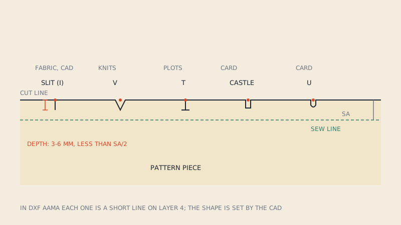
In a DXF AAMA file a notch is usually stored as a short straight line on layer 4. It starts on the piece's boundary and points into the piece; its position marks where the notch is, its direction gives the notch angle, and its length gives the depth. The notch shape you see on paper (a slit, a V, a T) is mostly not drawn in the file at all: the receiving CAD or cutter decides how to render or cut it.
That simple rule explains most missing-notch problems. If a file draws notches as little triangles on layer 0, or as marks that do not touch the boundary, the importing program has nothing it recognises as a notch.
What a notch is for, briefly
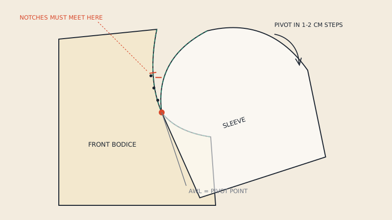
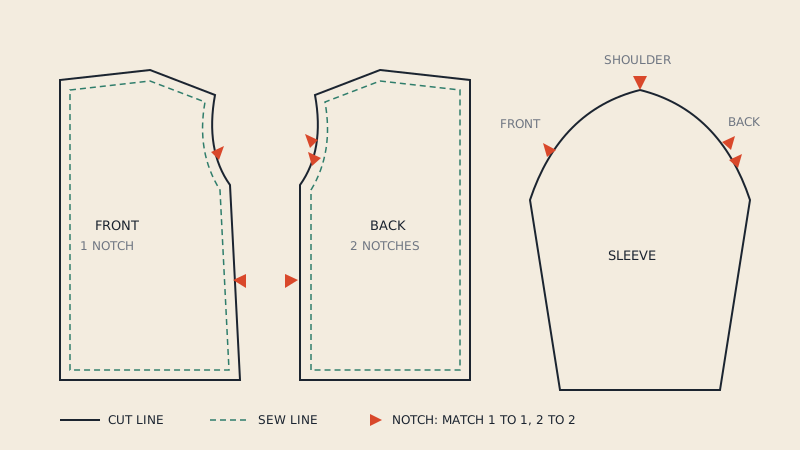
Notches are the alignment marks that tell you which edge joins which, and where: a single notch on a front armhole, a double on the back, a notch at the sleeve cap top. If you want the sewing side of notches, notches in sewing patterns covers reading and cutting them. Here we stay with how software stores them.
Anatomy of an AAMA notch
A notch in the file has three properties:
| Property | Stored as | Typical value |
|---|---|---|
| Position | The start point of the layer-4 line, lying on the layer-1 boundary | Exactly on the cut line |
| Angle | The direction of the line | Perpendicular to the edge, unless angled on purpose |
| Depth | The length of the line | Often 3–6 mm (1/8–1/4"); varies by house style |
Because the start point must lie on the boundary, notches belong to the piece's outline. Software walks along the cut line, finds each layer-4 line that touches it, and records a notch at that point. A line that starts 0.5 mm off the edge can be ignored or flagged, depending on the program's tolerance.
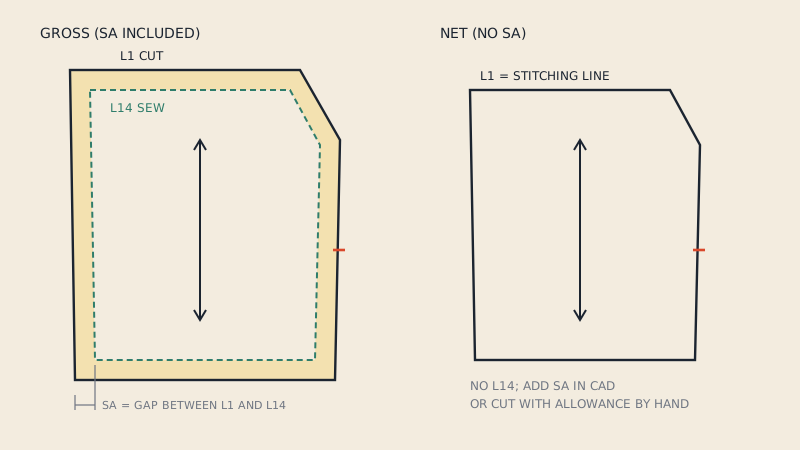
When a piece has both a cut line (layer 1) and a sew line (layer 14), the notch normally sits on the cut line and runs inward, past or up to the sew line. Some exporters attach notches to the sew line instead; most importers handle both, but it is worth knowing if your notches appear shifted by the seam allowance width. The seam allowance article explains the two lines.
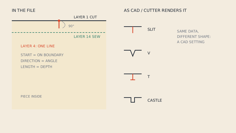
Notch types: drawn on paper, set in CAD
Industrial pattern making uses several notch shapes. On paper and in print files they are drawn; in CAD they are usually a property of the notch, chosen in the program or the cutter settings.
| Type | What it looks like | Common use |
|---|---|---|
| Slit (I) | A single straight cut into the seam allowance | The default in most production; easy for knife cutters |
| V | A small V-shaped wedge | Visible on thick or loose fabrics; common on home-sewing patterns as a triangle |
| T | A slit with a short crossbar at its end | Marks where stitching stops; also used for pivots |
| Castle (box, U) | A small rectangular notch | Used on some fabrics and by some cutters |
Some AAMA and ASTM exporters also write extra information about notch type, and ASTM D6673 added more structure than the original AAMA files. But a plain layer-4 line is the most widely read form. If notch shape matters for your cutter, check what your CAD writes and what the cutter's software reads. The types of notches article covers the shapes themselves.
Why notches go missing
Notches are the feature most often lost when a pattern changes format. The causes are predictable.
1. The notch was drawn as a shape, not a line
Home-sewing PDFs often draw notches as filled triangles outside the cut line, double triangles, or diamonds. A generic converter turns these into tiny closed shapes. Pattern CAD sees a triangle floating next to the piece, not a notch on its edge. In 3D software the triangle can even become a separate miniature piece.
2. The notch is on the wrong layer
Everything on layer 0, or notches on the same layer as the outline, means the importer cannot tell a notch from part of the boundary. A notch drawn as part of the outline becomes a little spike in the cut line, which is worse than no notch at all: it changes the piece shape and confuses seam lengths.
3. The notch does not touch the boundary
PDF marks are positioned by eye. A triangle may sit 1 mm outside the cut line, or a tick may cross it on both sides. If the line does not start on the boundary within the importer's tolerance, it is dropped or imported as a loose internal line.
4. The notch was cut off by a tile boundary
On print-at-home tiles, a notch close to the page edge can be split across two pages or partly hidden under the tile frame. Unless tiles are assembled first, the fragments do not form a recognisable mark.
5. The notch belongs to another size
In nested multi-size patterns each size can have its own notches at slightly different places, or all sizes share one notch drawn across the whole nest. Extract one size carelessly and you either get notches from neighbouring sizes or lose the shared one.
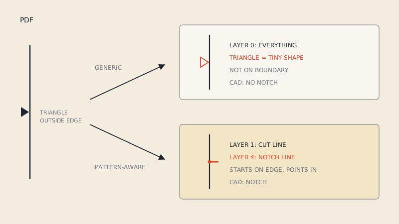
How a pattern-aware conversion handles notches
Converting a PDF properly means recognising each drawn mark as a notch, whatever its shape, and replacing it with a clean layer-4 line that starts exactly on the cut line and points inward. Double and triple notches become two or three lines. The mark's original shape is not kept as geometry, because that is the CAD's job.
Our converter does this and shows the notch count for every piece in the free preview, so you can compare it with the paper pattern before paying. If the count for a piece is off, that is the time to notice.
How to check notches after import
- Count per piece. Compare with the printed pattern. Front and back armholes, sleeve caps, side seams and waistbands are where counts matter most.
- Check pairs. A seam's two edges should carry matching notches: front side seam and back side seam, sleeve cap and armhole. Walking the seams in CAD confirms they line up.
- Look for spikes. Zoom along the cut line. A sharp spike in the outline is a notch merged into the boundary.
- Look for floating marks. Small triangles or ticks off the edge are notches the importer did not recognise.
- Check direction. A notch pointing outward, away from the piece, will be cut into the waste and lost on the fabric.
| Symptom | Likely cause | Fix |
|---|---|---|
| No notches at all | Notches not on layer 4, or drawn as shapes | Re-export or re-convert with notches as layer-4 lines |
| Spikes on the outline | Notches drawn as part of the cut line | Clean the outline; add notches with the CAD notch tool |
| Notches offset by SA width | Notches attached to the other line | Move them, or check the importer's cut/sew line setting |
| Extra notches | Notches from other sizes or tiles | Delete extras; extract one size cleanly |
| Notch shape wrong | Notch type is a CAD setting | Set type in CAD or cutter software |
FAQ
What layer are notches on in a DXF AAMA file?
Layer 4. Each notch is normally a short line that starts on the piece's boundary and points into the piece.
Does the DXF store whether a notch is a slit, V or T?
Usually not as drawn geometry. A plain AAMA notch is a short line, and the notch shape is chosen in the CAD program or cutter settings, although some exporters and ASTM files carry extra notch information.
Why did my notches turn into spikes on the pattern outline?
The notches were drawn as part of the cut line instead of as separate lines on layer 4. The outline now includes the notch shape, which distorts the piece; clean the outline and add notches with your CAD's notch tool.
Why do generic PDF to DXF converters lose notches?
They convert every drawn mark into loose geometry without knowing what it means. A triangle beside the cut line stays a triangle on layer 0 instead of becoming a layer-4 notch on the boundary.
How deep should a notch be in a DXF?
There is no single standard. Depths of about 3–6 mm (1/8–1/4") are common, and the notch should stay well inside the seam allowance.