Photo pattern digitizing means photographing a paper pattern on a flat surface and using software to correct the image so that measurements on it match the real pattern, then tracing or auto-detecting the pieces. It works well when three things are controlled: lens distortion, perspective (camera not square to the table), and scale, usually through a reference frame or markers of known size around the pattern. Without that calibration, a photo can look perfect and still be several millimetres off along a long edge.
Why a photo is not a measurement
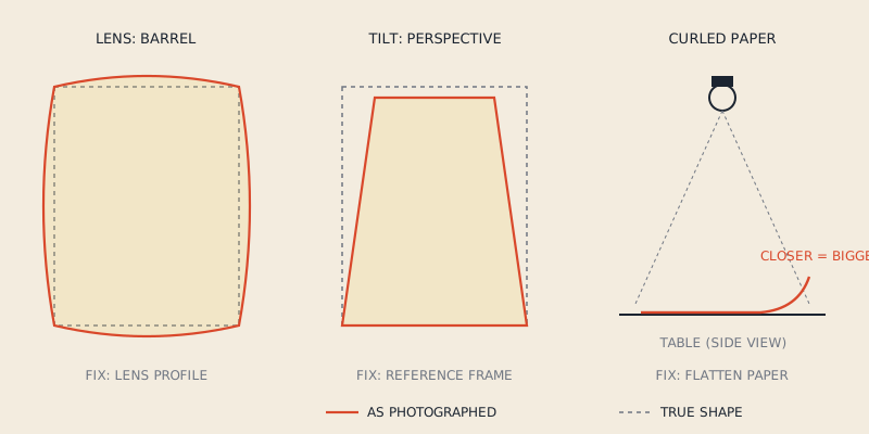
A camera does not see the table as a flat map. Three effects bend the picture:
- Lens distortion. Most lenses make straight lines near the edges of the frame bow outwards (barrel distortion) or inwards (pincushion). Wide-angle phone lenses tend to show it more.
- Perspective. If the camera is not exactly parallel to the table, the far side of the pattern appears smaller than the near side: a rectangle becomes a trapezoid.
- Height differences. Paper that curls, or a pattern lying on a slightly uneven surface, is closer to the camera in places and appears larger there.
Software can correct the first two if it knows enough about the camera and the geometry of the scene. It cannot easily fix the third, which is why flat paper matters as much as any calibration.
Calibration: what the software needs
Lens calibration
Lens distortion is a property of the camera and lens at a given zoom and focus. It is usually measured once by photographing a known pattern, such as a checkerboard or dot grid, from several angles, and letting the software compute a correction profile. After that, every photo from the same camera at the same settings can be undistorted.
Practical rules:
- Use the same camera, lens and zoom every time. Phone cameras switch lenses as you zoom, which changes the distortion.
- Turn off any "auto-correct" or beauty features that alter geometry.
- Keep focus at the table distance.
Perspective and scale: the reference frame
To correct perspective and set scale, the software needs known points on the table plane. Common options:
- A printed reference frame or border around the work area with markers at known positions.
- Markers at the corners of the table, measured once.
- A calibration mat with a printed grid under the pattern.
From four or more known points, the software computes how to map the photo back onto a flat, true-scale plane. More markers spread across the whole area give a better result than four markers close together.
Mounting
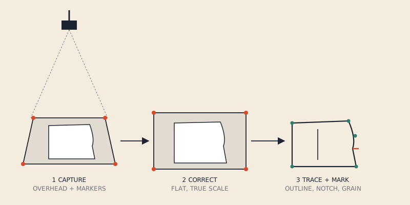
A fixed overhead mount, camera pointing straight down, is the single most useful piece of equipment. It keeps the geometry the same from photo to photo, so calibration stays valid and pieces are captured consistently. Handheld photos can work with a good reference frame, but each photo has to be corrected on its own and the results vary more.
How accurate can photo digitizing be?
Accuracy depends on the setup, so treat these as principles to reason with rather than promises.
Pixel size sets the floor
Divide the width of the captured area by the image width in pixels. As an illustration: a 150 cm wide area captured on an image 6,000 pixels wide gives 0.25 mm per pixel. You cannot reliably locate a line more precisely than about a pixel or two, so in this example the floor is around 0.25–0.5 mm, before any other error.
| Captured width (example) | Image width (example) | Size of one pixel |
|---|---|---|
| 60 cm | 4,000 px | 0.15 mm |
| 150 cm | 4,000 px | 0.375 mm |
| 150 cm | 6,000 px | 0.25 mm |
| 200 cm | 6,000 px | 0.33 mm |
These are arithmetic examples, not camera specifications. The point is the trade-off: a bigger area in one photo means bigger pixels.
Residual distortion adds on top
After correction, a small amount of distortion usually remains, typically largest near the edges of the frame. Place pieces towards the centre where you can, and test the edges separately.
Lines are wider than pixels
A pencil or printed line on a pattern can be 0.3–0.5 mm wide. Whether the software or person traces its centre or one edge makes a difference of the same order as the pixel size.
Testing your setup
Do not rely on calibration alone. Test with a known shape:
- Draw or print a large rectangle on paper with precisely measured sides, for example 100 × 60 cm, plus its diagonals.
- Photograph and digitize it with your normal workflow.
- Measure all four sides and both diagonals in the digital result.
- Compare with the real values. Sides tell you scale error; unequal diagonals tell you remaining skew or perspective.
- Repeat with the rectangle near the edge of the frame.
Record the largest error you see. That is your realistic tolerance, and it tells you which work the setup is good enough for. For home sewing a millimetre or two along a long seam is often acceptable; production patterns usually need tighter tolerances, which is one reason studios use digitizer boards or dedicated systems.
From corrected photo to pattern pieces
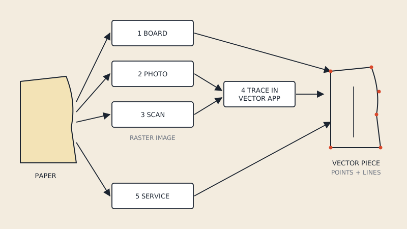
After correction, the image is a flat, scaled raster, much like a scan. The same next step applies: trace each piece as vector outlines, add notches, grain lines and internal lines, and label pieces. The scanning guide explains why a raster image is not yet a CAD pattern and how tracing works; it applies to corrected photos too.
Some photo-digitizing systems detect the outline automatically by contrast, which is why a plain, contrasting background helps: white pattern paper on a dark mat, or the reverse. Notches, grain lines and dart points usually still need to be marked by hand on screen.
Tips for better captures
- Flatten the paper. Weight the edges with thin, flat weights outside the outline, or use a sheet of glass. Curl is the error calibration cannot remove.
- Light evenly. Two lights at equal angles, no strong shadows along edges, no glare spots on glossy paper.
- Contrast. Background colour clearly different from the paper.
- One piece per photo if pieces are large, so each fills the well-calibrated centre.
- Include a check length. A ruler in each photo lets you spot problems immediately.
- Keep everything fixed. Same camera height, zoom and settings across a session.
Limits worth knowing
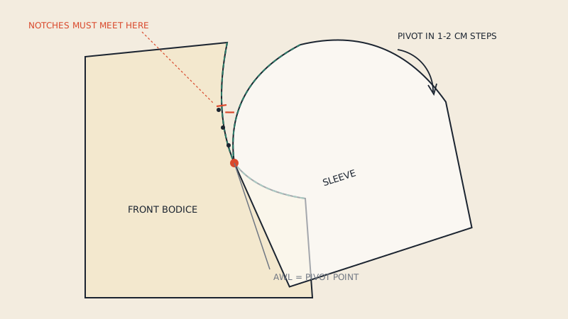
- Photo digitizing captures what is on the paper, including errors in the original pattern. Walk the seams of the result.
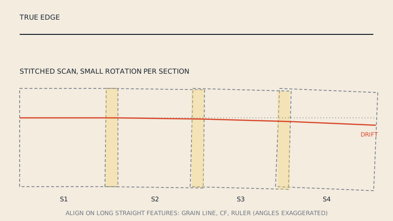
- Very large pieces may exceed what one photo can capture at the accuracy you need. Splitting them reintroduces stitching errors.
- Thin tissue, transparent paper and patterns with faint lines are harder for automatic detection.
Photos and PDF converters
If you are photographing a pattern because you only have it on paper, photo digitizing is a reasonable route. If you have the same pattern as a vector PDF, skip the camera: the lines in the file are already exact, and our converter extracts them into DXF AAMA. Our service does not process photos or scanned patterns. For the full set of options, see how to digitize sewing patterns.
FAQ
Can I digitize a sewing pattern with my phone camera?
Yes, if you calibrate for lens distortion, correct perspective with a reference frame or markers, keep the paper flat and test the result on a known rectangle. Uncalibrated phone photos are fine for reference, not for accurate pattern pieces.
What causes errors in photo pattern digitizing?
Lens distortion, the camera not being parallel to the table, paper curling towards the camera, and pixel size limiting how precisely a line can be located. Calibration handles the first two; flat paper and enough resolution handle the rest.
How do I check the accuracy of a photo-digitized pattern?
Digitize a precisely drawn rectangle with its diagonals using the same setup and compare all measurements with the real ones. Then check known measurements on the actual pattern, such as centre-back length.
Is photo digitizing as accurate as a digitizer board?
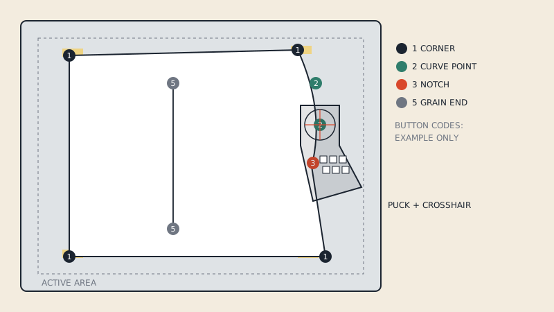
It can come close with a fixed mount, good calibration and flat paper, and it captures faster. A board avoids image distortion entirely, so for tight production tolerances it is often the more predictable choice.