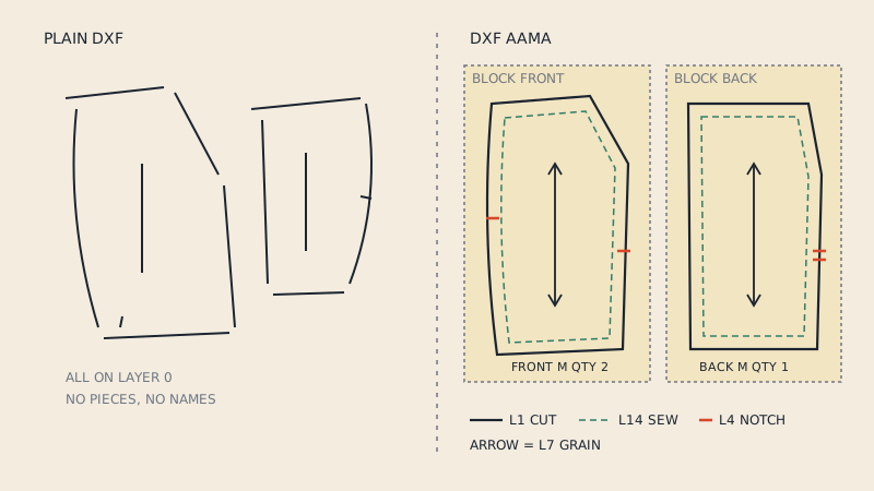
In the AAMA DXF format, the layer an entity sits on is its meaning. Layer 1 is the cut line, layer 4 holds notches, layer 7 the grain line, layer 8 internal lines, layer 14 the sew line, and a handful of other numbered layers carry turn points, mirror lines, drill holes and text. Pattern CAD reads these numbers to rebuild each piece. When a file puts every line on layer 0, the importer has nothing to go on and the pattern arrives as loose geometry.
This page is a working reference. For the background on why the format exists, see what is a DXF AAMA file.
The layer table
| Layer | Name | Typical entity | What pattern CAD does with it |
|---|---|---|---|
| 1 | Boundary (cut line) | Closed polyline | Becomes the piece outline |
| 2 | Turn points | Points on the boundary | Marks sharp corners |
| 3 | Curve points | Points on the boundary | Marks smooth points on curves |
| 4 | Notches | Short line or point at the edge | Becomes notches |
| 5 | Grade reference line | Line | Reference for grading movements |
| 6 | Mirror line | Two-point line | Fold line; piece can be opened |
| 7 | Grain line | Two-point line | Fabric direction |
| 8 | Internal lines | Lines and polylines | Darts, pleats, pocket and button placements |
| 9 | Stripe reference | Line | Matching stripes |
| 10 | Plaid reference | Line | Matching plaids |
| 11 | Internal cutouts | Closed polyline | Holes cut inside the piece |
| 13 | Drill holes | Points or small circles | Drill marks, dart points |
| 14 | Sew line | Polyline | Stitching line inside the cut line |
| 15 | Annotation text | Text | Free notes on the piece |
Not every file uses every layer. A converted single-size pattern typically has 1, 4, 7, 8 and 14, plus piece text. A graded file from industrial CAD often adds 2, 3 and 5. Layer 12 is not commonly used for apparel geometry, so it is left out above.
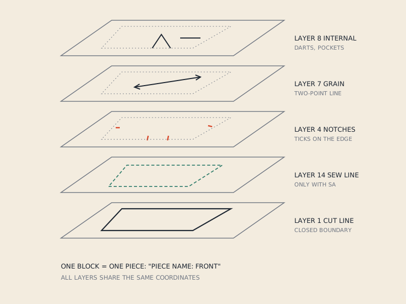
The layers that matter most
Layer 1: boundary
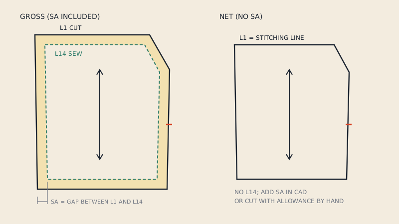
The outer cutting edge of the piece, written as one closed polyline. Everything else is positioned relative to it. If layer 1 is not closed, many programs either refuse the piece or import it as an open line that cannot be sewn or nested. A gap of a fraction of a millimetre is enough to cause this.
If the pattern has seam allowance, layer 1 is the edge with the allowance included. If the pattern is net (no seam allowance), layer 1 is the stitching line itself and layer 14 is absent. The difference is covered in detail in PDF to DXF with or without seam allowance.
Layers 2 and 3: turn and curve points
Points along the boundary that tell the receiving CAD which vertices are corners and which are part of a curve. Industrial systems use them to rebuild curves faithfully and to attach grade rules. Many 3D programs ignore them. Missing turn points rarely stop an import; they mainly affect how a piece behaves when you later edit or grade it.
Layer 4: notches
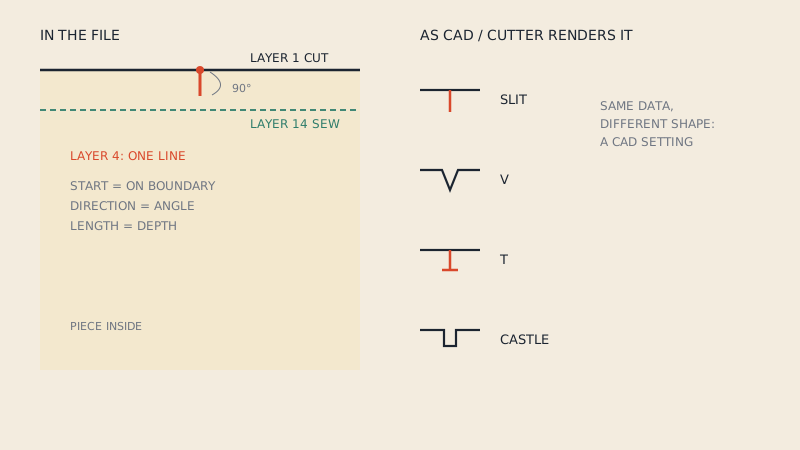
Each notch is usually a short line segment starting on the boundary and pointing into the piece, or a point on the boundary. The importing program turns it into a notch of its default type (slit, V, T and so on). Notches are what let you match seams, so losing them is a real problem; the common reasons they disappear are explained in how notches are stored in DXF AAMA.
Layer 6: mirror line
A line along an edge that should be cut on the fold. A program that understands it can show the half piece or open it into a full piece. If a file has a fold piece but no layer 6 line, you will have to unfold it manually after import.
Layer 7: grain line
A two-point line inside the piece. Its direction tells marker software how the piece may lie on the fabric and tells 3D software how to orient the fabric's warp. One grain line per piece. The arrowheads you see on paper patterns are decoration; the two endpoints are what count.
Layer 8: internal lines
Darts, pleat lines, pocket placements, buttonhole and button positions, centre front lines, fold lines inside a piece. Anything drawn inside the boundary that is not grain, text or a drill hole usually goes here. In CLO3D these come in as internal lines you can later fold or sew to.
Layer 13: drill holes
Points marking positions that the cutting room drills through a stack of fabric: dart points, pocket corners. Some pattern sources draw them as small circles rather than points; both are common.
Layer 14: sew line
The stitching line, drawn inside the cut line at the seam allowance distance. Its presence tells the receiving CAD that the piece is a gross pattern (seam allowance included) and where the actual seam runs. 3D programs can use it to sew on the stitching line rather than the cut edge.
Layer 15 and piece text
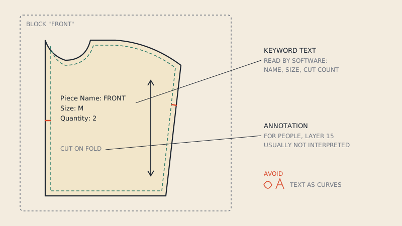
Free annotation goes on layer 15. The structured labels ("Piece Name:", "Size:", "Quantity:") are separate text entities inside the block and are read as piece properties; see piece names, sizes and quantities in a DXF pattern.
What goes wrong when everything is on layer 0
Layer 0 is the default layer in DXF. Generic converters, drawing programs and quick exports often put every line there. Here is what that does to an import:
- No outline is identified. The importer cannot tell the cut edge from a dart leg. Some programs then treat every closed shape as a piece, so a pocket placement rectangle becomes a "piece".
- Notches merge into the outline. A notch drawn as a tiny tick on layer 0 is just another segment. The cut line now has spikes and is no longer a clean closed shape.
- Grain is lost. The grain arrow becomes three or five loose lines. 3D software falls back to a default fabric direction, often wrong by 90 degrees.
- Seam allowance doubles. The sew line and cut line both look like outlines, so you may get two overlapping pieces, one slightly smaller.
- Text turns into geometry. If labels were converted to curves, the letters become dozens of tiny closed shapes.
The usual fix is to move entities onto the right layers in a CAD or DXF editor before importing, piece by piece. On a ten-piece pattern that is an hour or more of careful work; that kind of output is typical of generic tools, which is the subject of why generic PDF to DXF converters fail on sewing patterns.
How to inspect layers in a file
You do not need pattern CAD to check a DXF.
- Open the file in any free DXF viewer or in LibreCAD and open the layer list. You should see numbered layers, not only 0.
- Hide all layers except 1. Every piece should show a single closed outline.
- Show layer 4. Notches should sit on the outline, one tick per notch.
- Show layer 7. Each piece should have exactly one grain line.
- Open the file in a text editor and search for
Piece Name. You should find one per block.
Layer names sometimes carry a prefix or suffix depending on the exporter. Importers generally expect the plain numbers, so a file with layers named like CUT or L1 may need renaming before import.
Layers in converted files
Our PDF to DXF AAMA converter writes the cut line on layer 1, the sew line on layer 14 when the pattern has seam allowance, notches on layer 4, grain on layer 7 and internal lines such as darts, buttonholes and pocket placements on layer 8, with piece name, size and quantity in each block. The free preview lists these per piece, so you can see whether seam allowance and notches were found before you pay.
FAQ
What is layer 1 in an AAMA DXF file?
Layer 1 is the boundary, the closed outline of the pattern piece. If the pattern includes seam allowance, it is the cutting edge; if not, it is the stitching line.
Which layer are notches on in DXF AAMA?
Notches are on layer 4, usually as short lines starting on the boundary or as points on it. The importing CAD converts them into its own notch type.
What is layer 14 used for?
Layer 14 holds the sew line, the stitching line inside the cut line. It is present only when the piece includes seam allowance.
Why does my DXF have only layer 0?
The file was probably made by a general drawing program or a generic converter that does not follow the AAMA layer scheme. Pattern CAD cannot tell cut lines, notches and grain apart in such a file, so entities must be moved to the correct layers before import.
Where is the grain line in an AAMA file?
The grain line is a two-point line on layer 7 inside each piece. Its direction sets how the piece is placed on fabric in markers and 3D software.