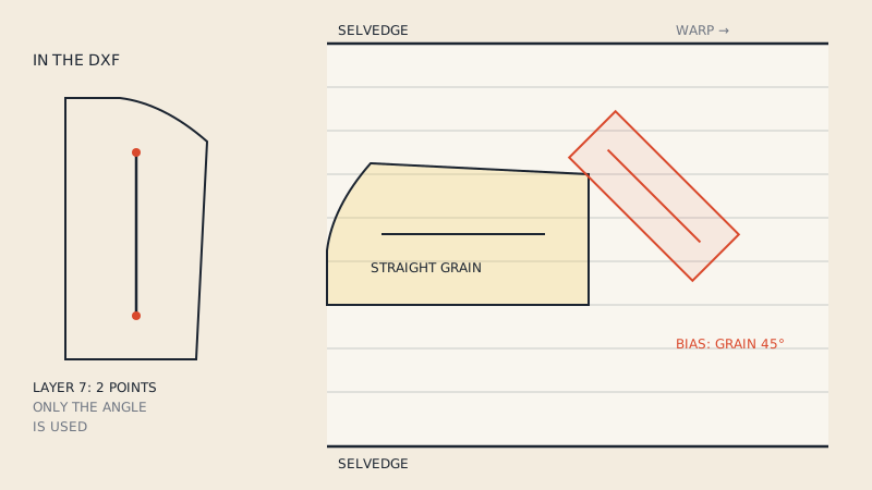
In a DXF AAMA pattern the grain line is a single straight line on layer 7, drawn inside the piece's block. Its two end points define a direction, and that direction tells every program downstream which way the fabric's lengthwise threads run through the piece. Marker software uses it to keep pieces aligned with the fabric; 3D software uses it to orient the fabric's weave and stretch, which changes how the garment drapes.
The arrowheads you see on paper are not needed in the file. What matters is the line's angle.
What the grain line means
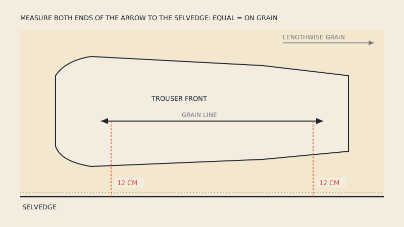
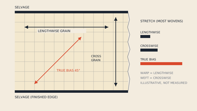
On a paper pattern the grain line is the long arrow you align parallel to the selvedge. It marks the lengthwise grain, the direction of the warp threads, which in woven fabric is the most stable direction. For how to place it on fabric, see grain line on a sewing pattern; for the difference between grain, cross grain and bias, see grainline vs selvage.
In a digital pattern the meaning is the same, but software acts on it automatically rather than you lining it up by eye.
How it is stored
| Property | In the DXF |
|---|---|
| Layer | 7 |
| Entity | A straight line (sometimes a two-point polyline) |
| Location | Inside the piece's BLOCK, usually within the outline |
| Information carried | Direction (the angle of the line); the length is just for display |
| Arrowheads | Not required; some exporters draw them as extra short lines |
One grain line per piece is the norm. The line does not have to be in any particular place inside the piece, and it can be any length. A 10 cm (4") line and a 60 cm (23 5/8") line in the same direction carry the same information.
The direction is an axis, not a vector, for most purposes: a grain line pointing "up" and one pointing "down" mean the same fabric alignment. Where up and down do matter, for napped fabrics such as velvet or corduroy and for one-way prints, CAD usually handles it as a separate piece or marker setting rather than reading it from the line.
How CAD and 3D software use it
Marker making
Nesting software rotates pieces to fit them tightly on the fabric width. The grain line limits that rotation: a piece may be flipped 180° along its grain, but not turned 90°, unless you allow it. Many marker programs also allow a small tilt tolerance, often expressed in degrees, for fabrics where a slight deviation is acceptable. Without a grain line, the software has no constraint and may place pieces at any angle, which looks efficient and produces garments that twist. Marker making basics has more on grain constraints.
3D garment simulation
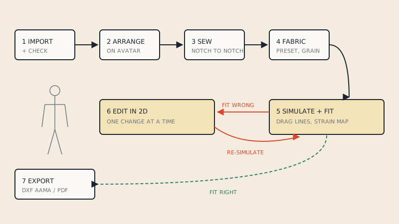
In CLO3D, Marvelous Designer and similar programs, each pattern piece has a fabric with different properties in the warp, weft and bias directions. The grain line sets which way the warp runs on that piece. Turn the grain 90° and a skirt cut on the straight grain behaves like one cut on the cross grain; set it at 45° and the simulation drapes it as a bias-cut piece, clinging and flaring more.
This is why a missing or wrong grain line can make a 3D sample look subtly off without any obvious error. The pieces are the right shape, the seams are sewn, but the fabric is behaving as if it were cut in the wrong direction. If you work in 3D, the CLO3D workflow article shows where grain fits into the sampling process.
Print layouts and plotting
When a CAD lays pieces out for printing, the grain line is drawn as an arrow so the person cutting can align it. Some layout tools also keep pieces aligned to the paper length by grain, which makes the printed pattern easier to check.
What happens without a grain line
| Situation | Result |
|---|---|
| No layer-7 line in the piece | CAD assumes a default (often vertical in the piece's own coordinates), or flags the piece |
| Grain drawn on layer 0 or the outline layer | Imported as an internal line or part of the boundary; no grain set |
| Grain line outside the block | Not linked to the piece; ignored or imported as a loose line |
| Grain drawn as an arrow made of several lines | Some importers read the first line, which may be an arrowhead at an odd angle |
| Two grain lines in one piece | Program uses one of them, not always the one you meant |
The "default vertical" behaviour hides a trap. If a piece was drafted with its grain vertical, the default happens to be right and nobody notices the line is missing. If the piece was drafted rotated, as many collars, bias facings and sleeve pieces are, the default is wrong and the fabric orientation in 3D or in the marker is wrong too.
Grain lines when converting a PDF
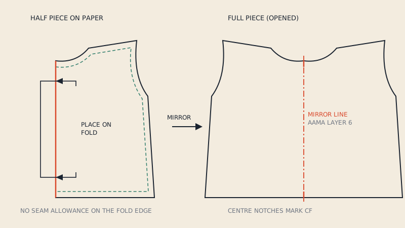
A PDF draws the grain line as an arrow: a straight line plus two arrowheads, sometimes with text such as "GRAIN" or "STRAIGHT GRAIN" along it, sometimes with a "place on fold" bracket instead. A pattern-aware conversion has to recognise that arrow, keep only its direction, and write one clean layer-7 line into the right piece.
The harder cases are:
- Fold brackets. A "place on fold" bracket implies grain parallel to the fold, without a separate arrow. See place on fold.
- Bias arrows on a piece that also has a straight-grain arrow for an alternative cut.
- Grain lines crossing tile boundaries on print-at-home files, split into two halves.
- Multi-size nests, where one grain arrow serves every size.
The free preview on our converter shows the grain line detected for each piece, so a missing or doubtful one is visible before you pay.
Checking grain after import
- Look at each piece. Every piece should show a grain line or grain indicator in your CAD or 3D program.
- Compare with the paper pattern. Bias pieces, rotated collars and cross-grain waistbands are where errors hide.
- Check pairs. Left and right fronts, or a sleeve and its mirror, should have mirrored grain.
- In 3D, check the fabric direction. Most 3D programs can show the fabric's texture or grain direction on the piece; a striped test fabric makes errors obvious.
- Fix in the program. CAD and 3D tools have a grain line tool; setting it by hand on a few pieces is quicker than re-exporting.
FAQ
Which DXF layer is the grain line on?
In the AAMA layer scheme the grain line is on layer 7. It is a straight line inside the piece's block, and its angle gives the fabric direction.
Does the length of a grain line in a DXF matter?
No. Only the direction matters. A short and a long grain line at the same angle mean the same thing; the length is for display and printing.
What does CLO3D do with the grain line from a DXF?
3D programs use the grain line to orient the fabric on each piece, so the warp, weft and bias properties act in the right directions. A wrong grain line makes the fabric drape as if it were cut in another direction.
What happens if a DXF pattern has no grain line?
Most programs fall back to a default direction, often vertical in the piece's own coordinates. That is right only if the piece was drafted with a vertical grain; rotated or bias pieces end up with the wrong fabric direction.
Do I need arrowheads on a DXF grain line?
No. Software reads the line's direction, not the arrowheads. Extra arrowhead lines can even confuse some importers if they are on the same layer.