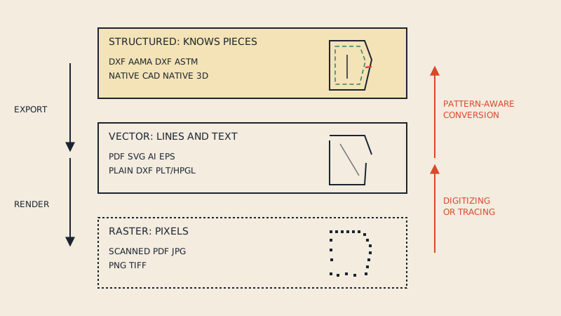
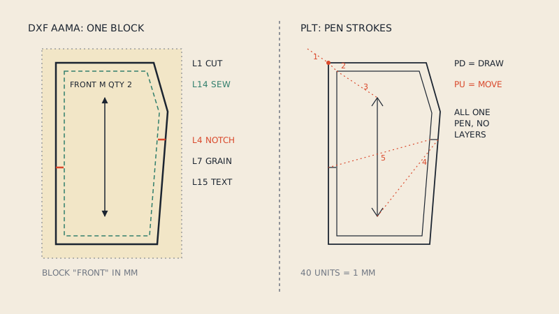
A PLT file is a set of instructions for a plotter, written in HPGL (Hewlett-Packard Graphics Language): lift the pen, move here, put the pen down, draw to there. Pattern CAD exports PLT to print or cut patterns and markers, so the file contains every line of the pattern, but it does not know that those lines form a front bodice with a grain line and three notches. That is the core difference from DXF AAMA, which stores pieces. Converting PLT to DXF is easy for the geometry and hard for the pattern structure, which has to be rebuilt.
Where PLT files come from
HPGL was created for HP's pen plotters, which drew technical drawings with real pens on paper. The language became a de facto standard: many plotters, cutters and later wide-format printers learned to understand it. Apparel CAD adopted it early, because pattern and marker plotting was one of the first jobs computers did in garment factories, and many systems still offer "plot to file" as PLT.
You typically meet PLT files when:
- A CAD system exports patterns or markers for a plotter or copy shop.
- A pattern supplier delivers PLT alongside PDF, for customers who plot.
- A cutting plotter or cutting table needs a file to cut card or fabric.
- You find old pattern archives from a factory that plotted everything.
What is inside a PLT file
PLT is plain text (in the classic form). A short, simplified example of the kind of commands you will see:
IN;
SP1;
PU0,0;
PD4000,0,4000,6000,0,6000,0,0;
PU2000,800;
PD2000,5200;
PU1200,3000;
LBFRONT;
What it means:
| Command | Meaning |
|---|---|
| IN | Initialize the plotter |
| SP1 | Select pen 1 |
| PU x,y | Pen up, move to x,y without drawing |
| PD x,y,... | Pen down, draw to each point in turn |
| PA / PR | Plot absolute / relative coordinates (sets how the numbers are read) |
| LB text | Draw a text label |
Coordinates are in plotter units. In HPGL, one plotter unit is 0.025 mm, so there are 40 units per millimetre (1016 per inch). In the example, the rectangle is 4000 x 6000 units, which is 100 x 150 mm (about 4 x 6"). Getting this conversion wrong is the most common reason a PLT opens at the wrong size.
HP-GL/2, the later version used by many large-format printers, adds features such as encoded polylines (more compact than plain text) and better line control. Some CAD exports use it, some use the original form, and some add vendor-specific commands.
What a PLT file does not contain
Because PLT was made to move a pen, everything that is not "draw this line" is missing or implicit:
- No pieces. Lines are not grouped. The outline of the front and the outline of the back are just strokes, one after the other.
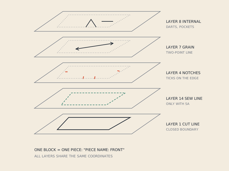
- No layers in the AAMA sense. There is no "layer 1 = cut line, layer 7 = grain line". The only grouping is the pen number, which CAD may use for different line types or for draw vs cut on a combined plotter, but with no fixed convention.
- No piece attributes. Name, size and quantity, if present at all, are text labels drawn as strokes or as LB commands, not data a program can read as "Quantity: 2".
- Curves are flattened. A smooth armhole becomes many short straight segments. Fine for plotting, less nice for editing.
- Notches are just short lines. A notch is indistinguishable from any other short stroke, unless you infer it from its position on the outline.
- Grain lines are lines. A grain arrow is a line with two short strokes for the arrowhead.
PLT vs DXF AAMA
| PLT / HPGL | DXF AAMA | |
|---|---|---|
| Purpose | Drive a plotter or cutter | Exchange pattern pieces between programs |
| Structure | Sequence of pen moves | One block per piece |
| Layers | Pen numbers, no standard meaning | Numbered layers with fixed meaning (1 cut, 4 notches, 7 grain, 8 internal, 14 sew line and more) |
| Piece name, size, quantity | Drawn text at best | Annotation text the CAD reads |
| Curves | Short straight segments | Polylines, often with curve points marked |
| Units | Plotter units (40 per mm) | Millimetres or inches |
| Opens in pattern CAD and 3D | Rarely, or as loose lines | Yes, as pieces |
| Good for | Printing and cutting | Editing, grading, 3D, markers, archiving |
The layer meanings are covered one by one in the AAMA DXF layers. The practical summary: PLT is an output, DXF AAMA is a working file.
Converting PLT to DXF
There are two levels of conversion, and it helps to know which one you need.
Level 1: geometry only
Translate every pen-down stroke into a DXF line or polyline, scaled from plotter units to millimetres. Many general CAD and file-conversion tools do this. The result is a plain DXF with the right lines at the right size, typically on a single layer.
This is enough if you want to:
- View or print the pattern.
- Trace over it in a vector program.
- Send the outlines to a laser cutter after cleaning up.
Level 2: pattern structure
To use the result in pattern CAD, 3D software or a marker system, you need AAMA pieces. That means:
- Split strokes into pieces: find closed outlines and group everything inside each one.
- Close the outlines: plotted outlines may be drawn in several strokes with tiny gaps.
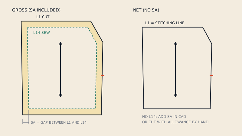
- Decide which outline is the cut line: if both cut and sew lines are plotted, assign them to layers 1 and 14; see cut line vs sew line in DXF.
- Identify grain lines and move them to layer 7.
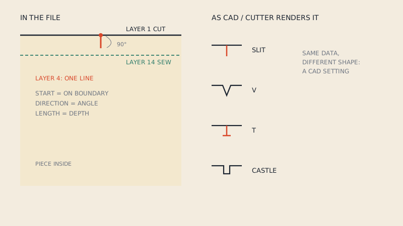
- Identify notches: short strokes crossing the outline, to layer 4. The AAMA notches article explains how they should be stored.
- Move internal lines (darts, pocket placements) to layer 8.
- Recover text: piece names and sizes, if they were plotted as LB labels, can be read; if they were plotted as strokes, they have to be retyped.
- Check the scale against a known measurement.
In practice this is done in pattern CAD with a PLT import function, if the program has one, or by importing the plain DXF and building pieces by hand. Some industry systems import their own plot files more cleverly because they know their own pen conventions.
Before you convert, ask for something better
If the PLT came from someone's CAD, the same system can almost always export DXF AAMA or ASTM directly. A one-line request saves hours of rebuilding. Likewise, if the pattern also exists as a vector PDF, a pattern-aware converter can build AAMA pieces from it; our PDF to DXF converter works from vector PDFs (it does not accept PLT). The pattern file formats overview shows the other conversion paths.
Checking a PLT file before plotting
If you are sending PLT to a plotter or copy shop rather than converting it:
- Open it in a viewer that understands HPGL and check that nothing is cut off.
- Confirm the width fits the roll; a marker for 150 cm fabric needs a plotter that wide.
- Check pens: if the file uses several pen numbers, make sure each maps to a visible line on the target device.
- Plot a test square or a reference line and measure along and across the roll. The pattern plotter guide describes the calibration steps.
- Do not let the driver scale the file to fit.
When PLT is the right format
- Sending a marker or pattern to a plotter or cutter that expects it.
- Delivering files to customers who own a plotter.
- Archiving exactly what was plotted for a production order.
For anything you might edit, grade, simulate or send to another program, keep DXF AAMA or the native CAD file as the master, and treat PLT as something you regenerate.
FAQ
What is a PLT file in pattern making?
It is a plotter file written in HPGL: a list of pen-up and pen-down moves that draw or cut the pattern lines. Pattern CAD exports it to print or cut patterns and markers.
Can I open a PLT pattern file in CLO3D?
Not as pattern pieces. 3D software expects DXF AAMA or ASTM with closed pieces and layers, so a PLT must first be converted and the pieces rebuilt.
Why does my PLT file open at the wrong size?
HPGL coordinates are in plotter units, 40 per millimetre. If a program reads them as millimetres or another unit, the pattern appears far too large or too small.
How do I convert PLT to DXF for pattern CAD?
Convert the strokes to DXF lines scaled to millimetres, then build pieces: close outlines, assign the cut line, grain line, notches and internal lines to AAMA layers, and add piece names. If the sender has the original CAD, asking for a DXF AAMA export is much quicker.
Is PLT the same as HPGL?
PLT is the usual file extension; HPGL (or HP-GL/2) is the language inside. Some CAD systems add their own commands, so not every PLT reads identically everywhere.