To print a DXF pattern you need three things: the pieces laid out at true size on a sheet or roll, that layout saved as a PDF without any scaling, and a test square so you can prove the print is 1:1. A DXF itself is not a print file. It is a set of pieces with no page around them, so something has to place them on paper first.
This guide covers the layout, the choice between one long sheet and tiled pages, the difference between plotting and printing, and the checks that catch scale errors before you cut.
Why you cannot just "print" a DXF
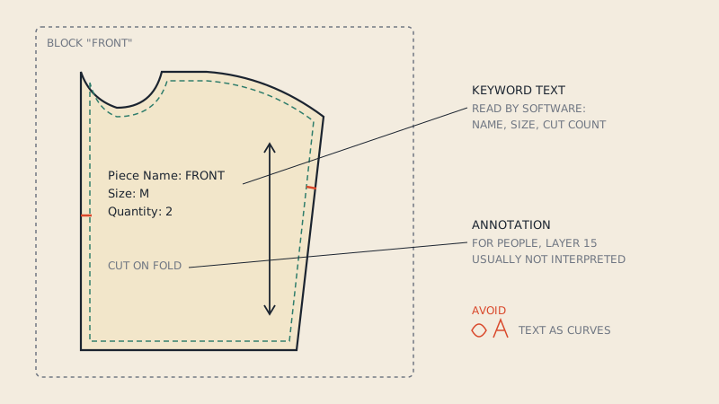
A DXF AAMA file stores each piece as a block at its real coordinates. Pieces can overlap, sit far apart or be rotated in odd ways, and there is no page size. Home printers, copy shops and PDF readers all expect a page with a known size.
So printing a DXF is really two jobs:
- Layout: arrange the pieces on a defined width (a roll) or area (a sheet), not overlapping, with grain lines in a sensible direction and a small gap between pieces.
- Output: write that layout to a format the printer understands, most often PDF, at 1:1.
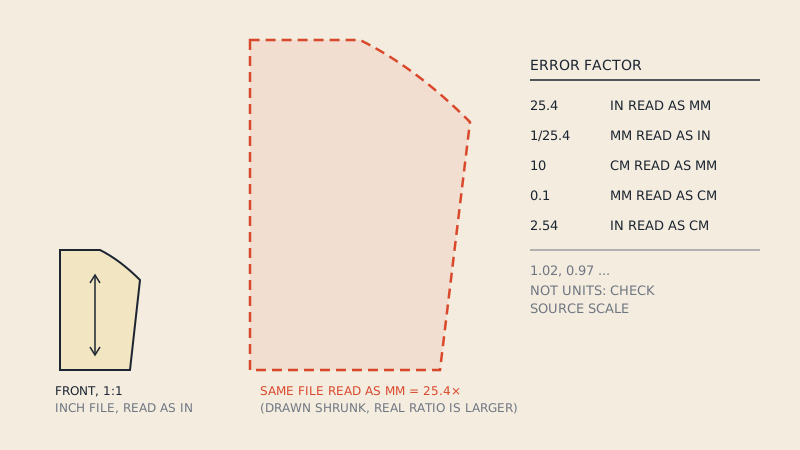
If your DXF imports at the wrong size in the first place, sort that out first; DXF units explains the 25.4× and 10× errors.
Step 1: choose the output width
Decide where the pattern will be printed before laying anything out, because the width drives the layout.
| Output | Printable width | Good for |
|---|---|---|
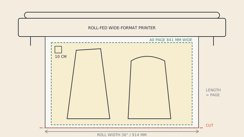
| A0 sheet | 841 mm (33.1") on the short side | Copy shops in metric countries |
| 36" roll | 914 mm (36") | Copy shops in the US and Canada |
| 80 cm roll layout | 800 mm (31.5") | Fits both A0 width and a 36" roll with margin |
| A4 tiles | 210 × 297 mm, minus printer margins | Home printing in most countries |
| US Letter tiles | 8.5 × 11" (216 × 279 mm), minus margins | Home printing in the US and Canada |
A layout about 80 cm wide is a practical choice: it fits on both A0 paper and a 36" roll with room for the printer's own margins. For the details of roll widths, see printing on a 36-inch roll.
Step 2: lay out the pieces
In pattern CAD this is often a "plot" or "print layout" function; in general CAD or a vector editor you place the pieces by hand. Whatever the tool, the rules are the same.
- Keep every piece at 100 %. Never use fit-to-page or zoom-to-sheet.
- Respect the grain. Rotating a piece 90° to save paper is fine on paper; mirroring is not, unless you mean it.
- Leave a gap of 1–2 cm (about 1/2") between pieces so they can be cut apart.
- Keep labels inside their pieces. Piece name, size and cut quantity should travel with the piece; see piece names and text in DXF.
- Keep notches, drill holes and internal lines. If they are on a layer you have hidden, they will not print.
- Mark place-on-fold edges. A half piece printed without its fold mark is easy to cut wrong.
Step 3: add a test square
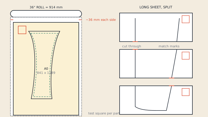
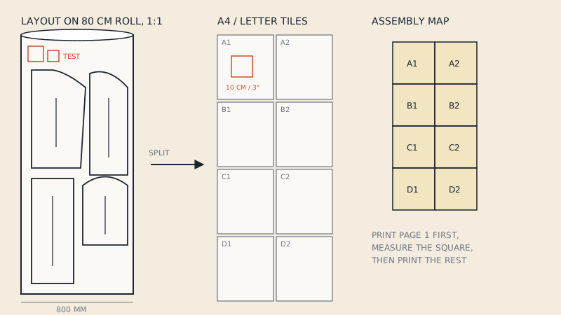
Put at least one test square on the layout, ideally both a 10 cm square and a 3" square, so people in either system can check it. On a long sheet, put it near the start. On tiles, put it on the first page.
The test square is the only honest proof that the print is 1:1, because a PDF can be scaled anywhere between your CAD and the paper. The test square guide explains how to measure it and what tolerance is acceptable.
Step 4: save as PDF without scaling
Most CAD programs can either export a PDF directly or print to a PDF printer driver. With a printer driver, check:
- Page size matches the layout (a custom size such as 800 × 2400 mm if it is one long sheet).
- Scale is 100 % or 1:1, not "fit".
- Lines are vector, not a rasterised image. Rasterised PDFs print fuzzy lines and become very heavy.
- Line weight is visible: hairlines can disappear on some plotters. A weight around 0.3–0.5 mm is commonly used for pattern lines.
Then open the PDF in a reader and measure the test square with the reader's measure tool, if it has one, before you send it anywhere.
Step 5: tile for home printing
To print on A4 or US Letter you split the long layout into a grid of pages with an overlap or a trim line, a page label on each (A1, A2, B1…) and an assembly map showing the grid. Each tile needs to stay inside the printable area of a typical home printer, so tiles are usually a little smaller than the paper.
Tiling by hand is slow; many CAD programs and PDF tools can do it. Whatever does the tiling, check that no line falls into the unprintable margin between tiles, or you will be joining pieces across a gap.
Plotting vs printing
These words get used loosely, but they mean different routes.
| Plotter route | PDF print route | |
|---|---|---|
| File sent | Often PLT/HPGL, sometimes PDF | |
| Device | Pen or inkjet plotter, roll-fed | Copy shop wide-format printer or home printer |
| Who uses it | Studios and factories with their own plotter | Home sewists, small studios, anyone without a plotter |
| Scale check | Plotter calibration | Test square on every print |
| Paper | Plotter paper, often 80–90 g/m² | Whatever the shop or printer loads |
If you have a studio plotter, your CAD probably plots DXF pieces directly and you may not need a PDF at all. The pattern plotter guide covers that side. For everyone else, PDF is the universal route.
Printing the PDF
- At a copy shop: ask for the file printed at 100 %, no scaling, on a roll or sheet wide enough for the layout, in black line. What to ask the copy shop has a checklist.
- At home: in the print dialog choose "Actual size" or 100 %; switch off any "Fit", "Shrink oversized pages" or "Scale to paper" option. Print page 1 first and measure the test square before printing the rest.
Common problems and fixes
| Problem | Likely cause | Fix |
|---|---|---|
| Test square 3–6 % small | Printed with "fit to page" | Reprint at 100 % / Actual size |
| Pieces 25.4× too small or big in the PDF | Wrong unit at DXF import | Re-import with the correct unit, redo layout |
| Notches or grain lines missing | Their layer hidden or not exported | Turn layers on before export |
| Piece names missing | Text layer off, or font not embedded | Include text layer; convert text if needed |
| Lines too thin to see | Hairline weight | Set a visible line weight before export |
| PDF hundreds of MB | Layout rasterised | Export as vector |
A quicker route
If you have a DXF AAMA from pattern CAD and just want print files, our converter accepts a DXF upload, lays the pieces out at 1:1 on an 80 cm roll and splits it into a One Page file plus A0, A1, A2, A3, A4 and US Letter sheets, each starting with 10 cm and 3" test squares and an assembly map, for €5 per pattern.
FAQ
Can I open a DXF pattern in a PDF reader?
No. PDF readers open PDF files only. You need CAD software or a conversion tool to place the DXF pieces on a page and save that as a PDF.
What scale should I use when exporting DXF to PDF?
Always 1:1, also shown as 100 % or "actual size". Any fit-to-page or zoom option changes the size of every piece, and a test square on the layout is the only reliable way to confirm the result.
How wide should the layout be for a copy shop?
It depends on the shop's paper. A layout about 80 cm (31.5") wide fits both A0 sheets (841 mm) and 36" rolls (914 mm) with room for printer margins.
Do I need a plotter to print DXF patterns?
No. A plotter can print DXF-based layouts directly, but most people export a PDF and print it at a copy shop or tile it on a home printer.
Why are some lines missing from my printed DXF pattern?
Usually the layer holding them was hidden or excluded when the PDF was made, or the line weight was a hairline the printer dropped. Turn on all pattern layers and set a visible line weight before exporting.